This blog has exclusively academic content as an Ad Honorem contribution to the research center of the Faculty of Petroleum and Natural Gas, Drilling chapter of the National University of Engineering. I am a Petroleum Engineer graduated from the National University of Engineering of Peru. I work in an oil and gas company as Sr. Drilling Engineer with more than 14 years of experience and working in different countries as a Argentina, Angola, Colombia, Venezuela and Perú.
Some professional challenges:
1.-Drilling Extended Reach wells in Camisea Project, Block 88 and 56. Well type "J" Cat.5 with Offshore in Land operations in Ucayali Basin going Through Vivian, Nia, Noi and Copacabana Formations. 2. Drilling Unconventional wells HP-HT in la Calera Project. Horizontal wells Cat.5 in Neuquén Basin going through Quintuco, Vaca Muerta, Tordillo formations. 3. Drilling Wildcats Exploration Wells in Ene Basin. Vertical wells, Cat.5 going Through Chonta, Raya, Cushabatay, Ambo formations. 4. Drilling Tight gas wells in Centenario Field. Wells type "S". Cat.3 in Neuquén Basin. Quintuco, Molles and Lajas formations. 5.Drilling Exploratory well in Angola. Vertical Wells Cat.4 in Congo Basin going through Pinda, Loeme ( evaporite), Lucula, Bucomazi, Mayombe Formations. 6. Drilling wells campaigns in the Jungle, Yanayacu, Corrientes, Jibarito and Capahuari Sur Fields. Wells type horizontal Cat.3 with offshore in Land in Marañon Basin going through Pebas, Chambira, Yahuarango, Vivian, Chonta, Agua Caliente, Raya, cushabatay formations. 7. Drilling Reentry wells campaign in the jungle in Corrientes, Capahuari Sur and Pavayacu Fields in Marañon Basin. Wells Cat3. Going through Lower Red Beds, Cachiyacu, Vivian formations. 8. Drilling training in Talara Basin. Vertical Wells Cat2. Marginal field going through Verdum, Pariñas Sup, Mogollon, Basal Salinas formations. 9. Training in Production in the jungle as design engineer in electric sumergible pump , gas lift and then as a Battery operator in Corrientes, Pavayacu and Saramuro, trainning in CCTQ, some challenges with heavy oil production ( 15 API) water drive reservoirs. 10. Start-up Family Business about Energy ABV Ingenieros Consultores SAC, about rural Electrification projects. Co-Founder ( Not related to the hydrocarbon sector).
Monday, July 27, 2020
5.- DRILLING BITS
Sunday, July 5, 2020
6.- DIRECTIONAL
When drilling a well there is a risk of serious damage caused by drillstring vibrations. Shock and vibration are identified as a cause of premature failure on drill bit and components in the bottom hole assembly (BHA), resulting in lost time for operators and costing service companies several millions in repair each year. The expenditures incurred by drillstring vibrations include reduced rate of penetration (ROP), tripping and poor drilling performance. Currently, several tools and techniques are used in the attempt to minimize shock and vibration. For vibration mitigation to be more effective in the future, the most effective tools and techniques must be designated, implemented and improved.
Predicting bottom hole assembly (BHA) vibrations is a complicated problem. Axial, lateral, and torsional vibrations can be coupled and effects such as stick-slip and whirl can magnify the loads. Fatigue, pipe bouncing, and tool joint washouts demon e the complexity of the problem. One type of vibration that can be isolated and analyzed is the rapid destruction of the BHA caused by operating at or close to resonance. At rotating speeds that reinforce the natural vibration of the BHA, the destructive harmonics generate high stresses resulting in very short fatigue life. While other factors may cause BHA failure, a significant percentage of field failures appear to be associated with harmonic vibration, particularly lateral vibration. A simplified model based on harmonic analysis using finite elements has been found to agree well with field experience. The influence of stabilizer placement, drill string forces, and mass of the drilling mud are included in the finite element vibration model. (SPE-16675-MS)
AXIAL VIBRATION : Can cause bit bounce , which may damage bit cutter and bearing.
TORSIONAL VIBRATION : Can cause irregular down - hole rotation. Stick/Slip is often seen while drilling and is a severe form of drillstring torsional oscillation in which the bit becomes stationary for a period. Torsional fluctuations fatigue Drill collars connections and can damage bits. The use of the mud motor may help to address if the main source of excitation is from the bit but the presences of a motor does not prevent stick/slip . The drillstring and BHA above the motor can enter into a stick/Slip motion even when the motor is turning the bit a steady rate.
Figure5 shows diagram for each of the three BHA configurations. Note that there are two stabilizers configured in BHA-2. The stabilizer is located at the far left to the bit in BHA-3 compare with BHA-2. There is one stabilizer used in BHA-1 near the bit. The detail descriptions are as following:
Figure6 provides state vectors display comparison for three of BHA surrogates operation at 100RPM and 80000N of bit weight. The lateral vibration potential simulation for BHA-1 is significantly lower than BHA 2 and BHA-3. Especially for the lateral displacement, the effect is most remarkably, which means that the contacts for BHA-1 with wellbore may be less than other BHA surrogates during drilling process. However, the yellow color curve shows the larger amplitudes of the states for BHA-2 than others, which represents the most severe vibration potential.
Update:24.07.19
Tuesday, February 18, 2020
7.- DRILLING FLUID
La Viscosidad del Lodo de Perforación cambiará cuando haya un cambio en la tasa de corte.
LSRYP : Low Shear Rate YP:
Debido a esta naturaleza del lodo se creó el término de “Viscosidad Efectiva” para compensar el cambio de la tasa de corte de la viscosidad. Por definición, la viscosidad efectiva es aquella viscosidad de un fluido Newtoniano que posee el mismo esfuerzo de corte a una misma tasa de corte.
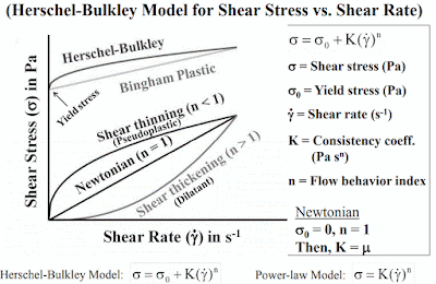
Herschel Bulkley
K : Índice de consistencia
n : Índice de Flujo.
n = 1: Fluido Newtoniano
n<1 : Fluido Pseudoplástico
Shear Stress = Yield Stress + K x (shear rate)n
Nota: El Yield Stress puede ser tomado de la lectura de 3 rpm y n y k son tomados de las lecturas de 600 rpm y 300 rpm.
Compresibilidad :
Recordemos que esta propiedad es típica del estado gaseoso, ya que los gases la poseen en grado notable; basta pensar que en primera aproximación (ley de Boyle), a una duplicación de presión corresponde una reducción de volumen a la mitad.
Pero la Compresibilidad, si bien en grado mucho menor, es también una propiedad de los líquidos.
Thursday, January 9, 2020
8.- SOLID CONTROL
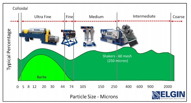
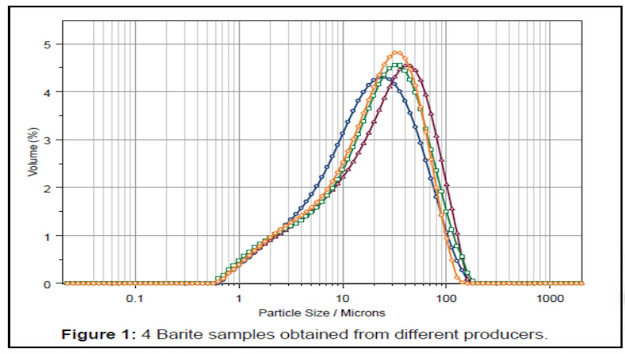
CLASIFICACIÓN TAMAÑO (API) DE SÓLIDOS :
PUNTOS DE CORTES POR ECS :
EFECTO TAMAÑO DE PARTÍCULA vs GELES
Saturday, January 4, 2020
9. - DOWNHOLE TOOLS
IMPULSO
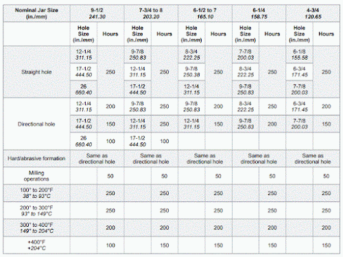
La determinación de la posición ideal del Martillo en el BHA es un problema complejo,
Los factores que deben ser considerados son:
- En zonas donde se anticipa la posibilidad de pega diferencial, ubique el Martillo ó Jar relativamente mas alto en el BHA para minimizar la posibilidad de quedar atrapado por encima del Martillo ó Jar.
- Para evitar cualquier acción inesperada del Martillo ó Jar en el fondo del pozo, El Jar debe mantenerse en tensión ubicada sobre el punto neutral de la sarta de perforación.
01 DC 9 1/2" ( 7 5/8" reg, ID: 3", 214.4 lb/ft, 81-97 Klb-ft) : 6,400 lb
01 DC 8" ( 6 5/8" reg, ID: 2 13/16, 148 lb/ft, 39-47 Klb-ft) : 4,400 lb
01 DC 6 1/2" ( NC50, ID 2 13/16, 90.6 lb/ft, 28-34 klb-ft) : 2,400 lb
01 HWDP 5 (NC50, ID: 3, 49.7 lb/ft, 28-33 klb-ft) : 1,400 lb
- Se debe colocar una cantidad suficiente de Drill Collar y / o tubería de perforación pesada HWDP sobre el Jar ó Martillo Hidráulico para proporcionar masa necesaria para golpear.
- Para evitar quedarse atascado sobre el Martillo ó Jar, la sarta de perforación de arriba no debe exceder el diámetro del Jar.
- Evite ubicar el Jar entre los componentes de BHA de diferentes diámetros, como
Collares y HWDP. El Jar debe colocarse un mínimo de dos juntas encima o debajo de un Crossover.
ESPECIFICACIONES TÉCNICAS ( MÁXIMO OVERPULL UP/DOWN)
Si se mantiene la circulación durante el trabajo de martilleo, la caída de presión a través de la broca crea una fuerza de apertura de la bomba que tiende a extender la tijera. La fuerza de apertura de la bomba debe considerarse en los siguientes cálculos, ya que
reduce la fuerza requerida para sacudir e incrementar la fuerza requerida para sacudir hacia abajo. La fuerza de apertura de la bomba se calcula multiplicando la caída de presión a través de la broca por el área abierta de la bomba.
ARRASTRE ( DRAG)
Puede requerirse una fuerza adicional para compensar el arrastre de las paredes del pozo, especialmente en pozos desviados. La cantidad de compensación debe determinarse a partir de las lecturas del indicador de peso durante el viaje antes de que la sarta de perforación se atasque.
PESO DE LA SARTA LIBRE
Es el peso de la sarta sobre el Martillo ó Jar. Para determinar el peso libre de la Sarta, reste el peso debajo del Jar del peso total de la Sarta.
