Some professional challenges:

1.-Drilling Extended Reach wells in Camisea Project, Block 88 and 56. Well type "J" Cat.5 with Offshore in Land operations in Ucayali Basin going Through Vivian, Nia, Noi and Copacabana Formations. 2. Drilling Unconventional wells HP-HT in la Calera Project. Horizontal wells Cat.5 in Neuquén Basin going through Quintuco, Vaca Muerta, Tordillo formations. 3. Drilling Wildcats Exploration Wells in Ene Basin. Vertical wells, Cat.5 going Through Chonta, Raya, Cushabatay, Ambo formations. 4. Drilling Tight gas wells in Centenario Field. Wells type "S". Cat.3 in Neuquén Basin. Quintuco, Molles and Lajas formations. 5.Drilling Exploratory well in Angola. Vertical Wells Cat.4 in Congo Basin going through Pinda, Loeme ( evaporite), Lucula, Bucomazi, Mayombe Formations. 6. Drilling wells campaigns in the Jungle, Yanayacu, Corrientes, Jibarito and Capahuari Sur Fields. Wells type horizontal Cat.3 with offshore in Land in Marañon Basin going through Pebas, Chambira, Yahuarango, Vivian, Chonta, Agua Caliente, Raya, cushabatay formations. 7. Drilling Reentry wells campaign in the jungle in Corrientes, Capahuari Sur and Pavayacu Fields in Marañon Basin. Wells Cat3. Going through Lower Red Beds, Cachiyacu, Vivian formations. 8. Drilling training in Talara Basin. Vertical Wells Cat2. Marginal field going through Verdum, Pariñas Sup, Mogollon, Basal Salinas formations. 9. Training in Production in the jungle as design engineer in electric sumergible pump , gas lift and then as a Battery operator in Corrientes, Pavayacu and Saramuro, trainning in CCTQ, some challenges with heavy oil production ( 15 API) water drive reservoirs. 10. Start-up Family Business about Energy ABV Ingenieros Consultores SAC, about rural Electrification projects. Co-Founder ( Not related to the hydrocarbon sector).


Friday, October 23, 2020

GEOLOGY II - SALT

Formación de depósitos de sal:

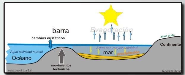
La sal se forma generalmente en dos ambientes. El primero, el más importante será el ambiente oceánico. Específicamente durante las épocas pérmica y terciaria en grandes cuencas marinas empezó una extensa precipitación de sales. La teoría de las barreras explica este evaporación por el cierre total o parcial de un brazo del océano. Sí el clima es árido o semiárido la taza de evaporación es mayor que la recuperación. Paulatinamente se aumenta la concentración de las sales en el agua y finalmente la sal tiene que precipitarse. Los enormes espesores y la ciclicidad de los depósitos pérmicos de sal apuntan a un proceso de múltiples fases
 
 
Las evaporitas aparecen en ambientes donde la salinidad de las aguas es superior a la normal, indicando como "salinidad normal" la salinidad promedio de los océanos o mares actuales (35g/l). Cuando la concentración de las sales aumenta se pasa de un ambiente marino normal a un ambiente penesalino (Nivel de salinidad intermedio entre marino normal e hipersalinas que oscila entre 72-352 ppm).


Las rocas evaporíticas son clasificadas basándose en su composición mineralógica y por lo tanto química. En esta forma las rocas evaporíticas pueden estar divididas en cuatro grandes grupos que son: carbonatos, sulfatos, cloruros y bromuros.

Carbonatos: calcita (CaCO3), dolomita (CaMg(CO3)2) y magnesita (MgCO3).
Sulfato: anhidrita (CaSO4) y yeso (CaSO4 2H2O).
Cloruros: halita (sal de mesa) (NaCl), silvita (KCl) y carnalita (KMgCl36H2O).
Boratos: bórax (Na2B4O5 (OH)4 8H2O).


Las evaporitas aparecen en ambientes donde la salinidad de las aguas es superior a la normal, indicando como "salinidad normal" la salinidad promedio de los océanos o mares actuales (35g/l). Cuando la concentración de las sales aumenta se pasa de un ambiente marino normal a un ambiente penesalino (Nivel de salinidad intermedio entre marino normal e hipersalinas que oscila entre 72-352 ppm). 
 
 
Formación de un domo de sal:


El bajo peso específico de la sal y la deformación plástica son los dos factores más importantes que empujan un movimiento de grandes masas de sal hacía arriba. Lentamente la sal se busca una manera para subir. Generalmente a lo largo de estructuras tectónicas (fallas por ejemplo) la sal encuentra un sector débil, que permite una expansión hacía arriba.
Los domos de sal tienen una estructura interna sumamente complicada, específicamente un fuerte plegamiento. También el sector de contacto con las rocas más jóvenes se ve intensamente afectado por las fuerzas de la subida de la estructura.


Según estudios geomecánicos realizados en el Golfo de México se determinó que la velocidad a la que se mueve la sal depende de la profundidad a la que se encuentra, la temperatura de la formación, la composición mineralógica, contenido de agua y la presencia de impurezas tales como arcillas. De estos estudios se pudo observar que los cloruros y sulfatos de sales que contengan agua como la carnalita y la silvita son los más móviles, que la halita es relativamente lento su movimiento, y que la anhidrita y los carbonatos (calcita, dolomita) son esencialmente inmóviles.

El exceso de movimiento que se observó en los estudios realizados en el Golfo de México fue de hasta 1 pulgada / hora. 

En contraste, para sales denominadas como una sal "limpia" (halita) no muestra ningún movimiento, es prácticamente inmóvil, cabe aclarar que la movilidad está fuertemente afectada por las condiciones de temperatura, contenido de agua y presión a la que se encuentra.


Ventajas en la perforación de sal 
La sal de hecho proporciona una serie de ventajas para la perforación: 


(1). Tiene un gradiente de fractura (Gf) mucho mayor al gradiente de sedimentos adyacentes para una determinada profundidad. 
(2). La ventaja de perforar en la sal, es la capacidad de reducir significativamente el riesgo de situaciones de control. 
 
 Desventajas en la perforación de sal 

La sal también tiene tres desventajas principales:
(1). Es una formación mucho más difícil para ver por métodos sísmicos. 
(2). La presión de los poros de las formaciones inferiores son elevadas. 
(3). La dureza de la sal hace difícil el control direccional. 

 Variaciones en el agujero (Descalibre de pozo
Una mala selección de las propiedades del lodo de perforación en el caso del lodo base agua pueden crear diferentes diámetros en el pozo por efecto de la disolución de las paredes de la sal causando problemas en el asentamiento de la tubería de revestimiento, al finalizar la etapa por tener un agujero mal configurado, (fuera de calibre) que aunque la afluencia de la sal podría estabilizar se debe considerar que la estructura no tiene la misma composición mineralógica en las distintas profundidades lo que podría provocar que algunas partes permanezcan inmóviles lo que deja un pozo irregular, lo que acarrearía serios problemas en la cementación primaria de la TR aumentando los costos de la perforación al tener que realizar cementaciones forzadas. 


El cierre de la sal aumenta la carga sobre la tubería de revestimiento y el cemento ya que ambos deben ser capaces de resistir las fuerzas aplicadas por la sal que se expande radialmente en algunas ocasiones no homogéneamente y aprieta el pozo, como se muestra en la Fig.3.4, por lo que se deben considerar estas condiciones en el diseño de asentamiento de las tuberías de revestimiento (TR) considerando una resistencia al colapso alta.


GEOLOGY III - CLAY

123


google.com, pub-8657610290366511, DIRECT, f08c47fec0942fa0

GEOLOGY IV - SAND


google.com, pub-8657610290366511, DIRECT, f08c47fec0942fa0

PIPE INSPECTION

123


google.com, pub-8657610290366511, DIRECT, f08c47fec0942fa0

TORQU & DRAG

123


google.com, pub-8657610290366511, DIRECT, f08c47fec0942fa0

DRILLPIPE

123


google.com, pub-8657610290366511, DIRECT, f08c47fec0942fa0

LOST CIRCULATION

123

WELLHEAD

123


google.com, pub-8657610290366511, DIRECT, f08c47fec0942fa0

WIRELINE

123

CASING


CORROSIÓN


Tipos de corrosión:
Corrosión por CO2
pPCO2 > 30 psi ( cuidado)
%CO2 milar > 0.5% 

Corrosión por  H2S

Bacterias: Sulfato-reductoras ( se agrega en el proceso de fractura)


Mediciones:
1.- Modelos de corrosión: 

- Norsok M 506-2017  ( velocidad de corrosión)
- Modelo OLI ( modelamiento PH)
- Modelo de flujo transiente

2.- Registro Multifinger ( 14 brazos, 36 brazos o palpadores )
ejemplo Expro, Delpa P, 

- Tiempo cero T=0
- Tiempo T= 6 meses de producción, T=12 meses, T=18 meses
Se considera 15% - 18% como normal parte de la manufactura en el diámetro. lo adicional es para el cálculo de Corrosión.

3.- En caso de mayor presupuesto evaluar USIT

4.- Velocidad string para reducir velocidad de corrosión, como protección mecánica. 
En caso de 0.5% Molar de CO2 evaluar el uso de Coild Tubing Cra ( 19% de cromo)
pPCO2: mayores de 30 psi

En las profundidades donde es alto MPY evaluar usar niveles de Cr 3, Cr 13, etc...   

5.- Revisar espesor de casing en especial zona Helicoidal durante el running ( caso desviaciones de la vertical). se observa errores en la data del caliper y se incrementa si no esta centralizado.

6.- P 110 no recomendable en ambientes corrosivos. Soluciones: migrar a un N80 o a un Cr3.   

7.- Velocidad de corrosión sigue aumentando a pesar que se cierre el pozo.

Muestra del agua de producción:

Condición normal
0.4 mm/año : Tubing
0.25 mm/año : Casing 
Velocidad de corrosión : 0.05 mm/año (moderado)

Nota: MPY: mili pulgadas por año

Condición ALARP
CO2 : 0.5% Molar

Condición Sour
pPH2S : 0.077 , presión parcial (psi)
H2S ppm : 10 ppm
Velocidad de corrosión: 10 mm/año
CO2 : 1% Molar

Valores altos : 5% , 15% , 20% ,  molar de CO2.
[ material sandnicro28 ]

Gráfica NKK 

BIF DIFERIDA:


TIPOS DE TUBING:
Acero al carbono (CS)
Cr3
Cr13

FACTORES QUE INFLUYEN EN LA CORROSIÓN
Temperatura , CO2, H2S, 


SLICK LINE

123


google.com, pub-8657610290366511, DIRECT, f08c47fec0942fa0

TECHNOLOGY

123

Friday, September 4, 2020

2.- PROJECT EVALUATION

RISK ASSESSMENT FOR OIL AND GAS PROJECT 

Risk assessment can be used in many ways. In oil and gas construction activity focus about the safety risk assessment , which in general is qualitative. For the project management it can be used in cost estimation to define the contingency.  There are many softwares that are based on Monte-Carlo simulation, the best one is the Crystal-ball software.

Exploration Risk :

– Existence of Hydrocarbons
– Magnitude of Discovery
– Type of Hydrocarbon

Development Risk :
– Technical Risk 
– Reservoir Development

The ALARP principle - as low as reasonably practicable

The ALARP principle is sometimes used in the oil and gas industry . The use of the ALARP principle may be interpreted as, satisfying a requirement to keep the risk level “as low as possible” provided that the ALARP evaluations are extensively documented. In the ALARP region (between “lower tolerable limit” and “upper tolerable limit”), the risk is tolerable, only if risk reduction is impracticable or if its cost is grossly disproportionate to the improvement gained. The common way to determine what is practicable is to use cost–benefit evaluations as a basis for the decision on whether certain risk reducing measures should be implemented. A risk may not be justified in any ordinary circumstance, if it is higher than the “upper tolerable limit.” The “upper tolerable limit” is usually defined, whereas the “lower tolerable limit” may sometimes be left undefined. This will not prohibit effective use of the approach, as it implies that ALARP evaluations of risk reducing measures will always be required. The ALARP principle used for risk acceptance is applicable to risks regarding personnel, the environment, and assets.

Layers of Protection Analysis (LOPA)


Percentil P10, P50, Pmean, P90 : 

One technique that the industry uses to understand and quantify distributions of data is percentiles (or cumulative probabilities). This organizes the distribution into increments between 0 and 100. For example, the 10th percentile or P10 number  say 10 percent of my wells will have a value “less than or equal to” my P10 value. The location of percentiles on a typical lognormal distribution would look something like:


Comparing to the P10, which could potentially give estimates that are over-optimistic, and the P90, a conservative estimate which could potentially leave too much oil, both providing confusing future trends. It is a common misunderstanding that the P50 is a synonym of P mean. This will be true is the probability distribution function for the observations were symmetrical. In this case, the mode, P mean and P50 would all be the same.


CAPEX : Capital expenditures are major purchases a company makes that are designed to be used over the long-term. 

- Platform   : Services + Materials + Logistic
- Well         : Drilling Cost ( Services + Tangibles) 
- Facilities  : Lines + Tanks + Separators 

OPEX : Operating expenses are the day-to-day expenses a company incurs to keep their business operational.

- Rent and utilities
- Wages and salaries
- Accounting and legal fees
- Royalties 
- Property taxes
- Business travel

Lifting Cost = OPEX / Production ( $/bbl ) 

1.- Cash flow (n=0) : CAPEX
2.- Cash flow (n=1) : Oil Price ( PRMS or Portfolio )  x Q ( Oil Production) -  OPEX | Year 1
3.- Cash flow (n=2) : Oil Price ( PRMS or Portfolio )  x Q ( Oil Production) -  OPEX | Year 2

PETROLEUM RESOURCE MANAGEMENT SYSTEM (PRMS) 

In 2000, the American Association of Petroleum Geologists (AAPG), SPE, and the World Petroleum Council (WPC) jointly developed a classification system for all petroleum resources. This was followed by complementary application evaluation guidelines (2001), standards for estimation and Audit of Reserves information (2001, 2007 revised version) and a glossary of terms used in the definitions of resources (2005).


(*) For Oil Production : Require to have database production data  in OFM Software for example. 

ARPS
Exponential Declination ( b=0)   : 
Hiperbolic Declination ( 0<b<1)  : 
Switch Point : change Transient flow to Boundary flow.


EUR : using declination curve : ARPS , Fetkovich, Duong, etc...  Depend of reservoirs type. 

SPE/WPC/AAPG (2000) : 

- Proved    >= P90 (1P)
- Probable >= P50 (2P)
- Possible >=  P10 (3P)

OOIP & OGIP

· N = OOIP (STB)

· 7758 = conversion factor from acre-ft to bbl

· A = area of reservoir (acres) from map data

· h = height or thickness of pay zone (ft) from log and/or core data

· ø = porosity (decimal) from log and/or core data

· Sw = connate water saturation (decimal) from log and/or core data

· Boi = formation volume factor for oil at initial conditions (reservoir bbl/STB) from lab data


· G = OGIP(SCF)

· 43560 = conversion factor from acre-ft to ft3

· Bgi = formation volume factor for gas at initial conditions (reservoir ft3/SCF)


·         Solution gas                   : 18 – 25%

·         Expansion                      : 2 – 5%

·         Gas cap drive                 : 20 – 40%

·         Water Drive (bottom)      : 20 – 40%

·         Water Drive (Edge)         : 35 – 60%

·         Gravity                            : 50 – 70%


Recovery Oil reserve = OOIP or OGIP x RF


NET PRESENT VALUE (NPV) : 
Net Present Value (NPV) is the value of all future cash flows (positive and negative) over the entire life of an investment discounted to the present.

"D" represents the value of the cash flows for each of the exercises, "i" the interest rate expected to be obtained or the rate of return of an investment of risk and similar duration and "n" the number of periods that it is estimated of the operation of the company.


Cash Outflows (expenditure)

  • Initial investment to purchase assets
  • Operating costs such as labor and materials
  • Tax payments
  • Project management expenses
  • Any other outflow caused by accepting the project

Cash Inflows (income)

  • Project revenues and grants
  • Eventual scrap value of assets
  • Any other inflow caused by accepting the project


CRYSTAL BALL CHART

- Red área = Cash Flow negative
- Blue área = Cash flow positive


CONTRIBUTION TO THE VARIANCE NPV


INDEX


3.- LOGISTIC


ICC ( International Chamber of Commerce)  has launched Incoterms 2020 , the newest edition of the renowned trade terms for the delivery of goods, providing certainty and clarity to business and traders everywhere. Incoterms 2020 includes more detailed explanatory notes with enhanced graphics to illustrate the responsibilities of importers and exporters for each Incoterms rule. The introduction to Incoterms 2020 also includes a more detailed explanation on how to choose the most appropriate Incoterms rule for a given transaction, or how a sales contract interacts with ancillary contracts.


MI vs CHINOOK ( HEAVY LIFT) 

IMPROVED LIFT CAPABILITY 


ENHANCED LANDING APPROACH CAPABILITY


SMALLER ROTOR BLADE


DOWNWASH IMPACT


Monday, August 24, 2020

4.- DRILLING RIGS


DRILLING BARGES : A drilling barge consists of a barge with a complete drilling rig and ancillary equipment constructed on it. Drilling barges are suitable for calm shallow waters (mostly inland applications) and are not able to withstand the water movement experienced in deeper, open water situations. When a drilling barge is moved from one location to another, the barge floats on the water and is pulled by tugs. When a drilling barge is stationed on the drill site, the barge can be anchored in the floating mode or in some way supported on the bottom. The bottom-support barges may be submerged to rest on the bottom or they may be raised on posts or jacked-up on legs above the water. The most common drilling barges are inland water barge drilling rigs that are used to drill wells in lakes, rivers, canals, swamps, marshes, shallow inland bays, and areas where the water covering the drill site in not too deep.

SUBMERSIBLES RIGS: Submersible drilling rigs are similar to barge rigs but suitable for open ocean waters of relative shallow depth. The drilling structure is supported by large submerged pontoons that are flooded and rest on the seafloor when drilling. After the well is completed, the water is
pumped out of the tanks to restore buoyancy and the vessel is towed to the next location. 

JACK - UP RIGS: 
Jack-up drilling rigs are similar to a drilling barge because the complete drilling rig is built on a floating hull that must be moved between locations with tug boats. Jack-ups are the most common offshore bottom-supported type of drilling rig. Once on location, a jack-up rig is raised above the water on legs that extend to the seafloor for support. Jack-ups can operate in open water or can be designed to move over and drill through conductor pipes in a production platform. Jack-up rigs come with various leg lengths and depth capabilities (based on load capacity and power ratings). They can be operated in shallow waters and moderate water depths up to about 450 ft.

SEMI - SUBMERSIBLE RIG: Semi-submersible drilling rigs are the most common type of offshore floating drilling rigs and can operate in deep water and usually move from location to location under their own power. They partially flood their pontoons for achieving the desired height above the water and to establish stability. “Semis” as they are called may be held in place over the location by mooring lines attached to seafloor anchors or may be held in place by adjustable thrusters (propellers) which are rotated to hold the vessel over the desired location (called dynamically positioned).


DRILLSHIP:   Drillships are large ships designed for offshore drilling operations and can operate in deepwater. They are built on traditional ship hulls such as used for supertankers and cargo ships and move from location to location under their own power. Drillships can be quite large with many being 800 ft in length and over 100 ft in width. Drillships are not as stable in rough seas as semi-submersibles but have the advantage of having significantly more storage capacity. Modern deepwater drillships use the dynamic positioning system (as mentioned above for semisubmersibles) for maintaining their position over the drilling location. Because of their large sizes, drillships can work for extended periods without the need for constant resupply. Drillships operate at higher cruising speeds (between drillsite locations) than semi-submersibles.


WELL SERVICES ENGINES

Drilling rigs use direct current generators and motors that have an approximate efficiency of 68%. Actual efficiency in conjunction with drilling machinery is 87.5% due to additional losses in the power requirements of field induction generators, cooling blower, commutator temperature, brushes, and feeder cable length. In this system, the available energy is limited for the reason that only one DC generator. can be electrically linked to a DC motor. resulting in 1600 H.P. available to drive the winch. 

DC (SCR) Drilling Rig

On a DC drilling rig, alternate current (AC) produced by one or more AC generator sets is converted into direct current (DC) by means of a silicon-controlled-rectifier (SCR) system. They obtain an efficiency of 68%; whose available energy is concentrated in a common bar (PCR) and can be partially or totally channeled to the drilling machinery (rotary, winch and pumps) that is required.


AC (VFD) Drilling Rig On an AC powered rig, AC generator sets (diesel engine plus AC generator) produce alternating current that is operated at variable speed via a variable-frequency drive (VFD)

AC versus DC Drilling Rig
Apart from being more energy efficient, AC powered rigs allow the drilling operator to more accurately control the rig equipment, thus enhancing rig safety and reducing drilling time.


AC Drilling Rig Advantages

- Efficient energy consumption due to a high power factor (minimum 95%).
- Precise speed regulation over a wider speed range.
- Constant high power even at low speed.
- Full torque at zero speed.
- Regenerative braking for safe and efficient control of the drawworks.
- Convenient and safe autodriller system for managing and controlling parameters such as weight on bit (WOB), rate of penetration (ROP), and rotary torque control.

CAT 3512B : Average rating: 1000 kw 

CAT 3512B : Average rating: 1000 kw